Appendix: General Status Model
Description
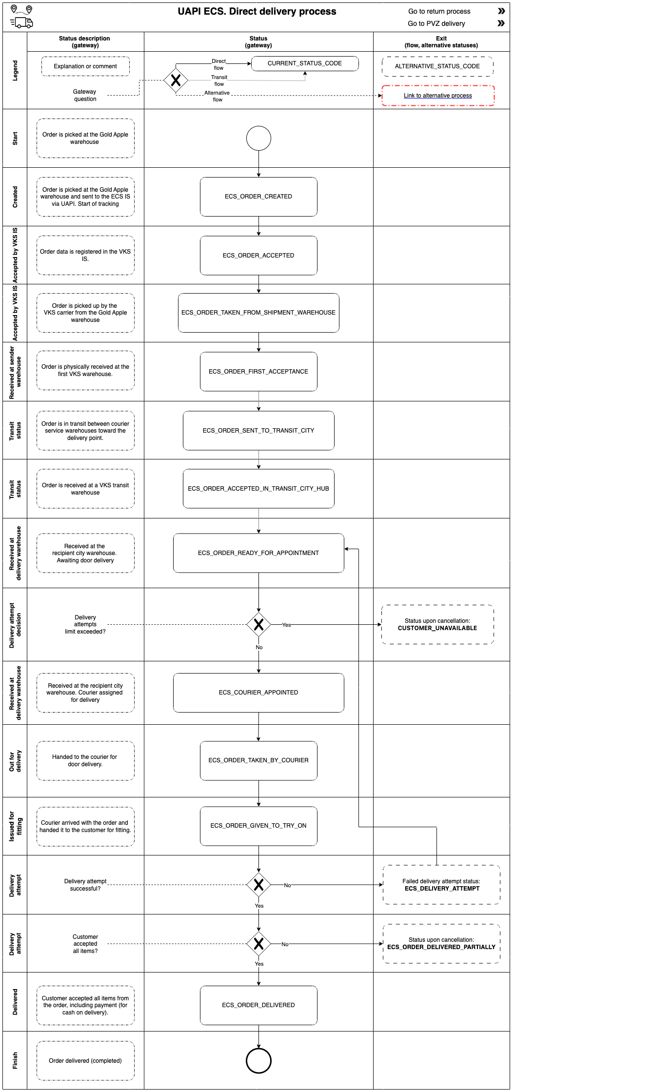
The diagrams presented below are, in essence, a single diagram split into different layers. The "General State Transition Diagram" section presents the overall diagram, with links to the layers. For convenient navigation between layers, there is a navigation control in the upper-left corner of the pool on each layer. The diagrams in the return and PP-delivery sections are links to layers of the original "UAPI ECS. General Status Model" diagram.
Legend
BPMN notation is used as the starting point, but it has been modified:
- Links to other layers within sub-processes are highlighted with a red dashed outline in the shape of a Data Object;
- Start and end events follow BPMN notation — circles with a thin and a thick outline, respectively;
- Any empty task contains a tracking status;
- Any data object that is not highlighted is an explanation of a state (status);
- Pools contain status rows in a table-like arrangement.
General State Transition Diagram
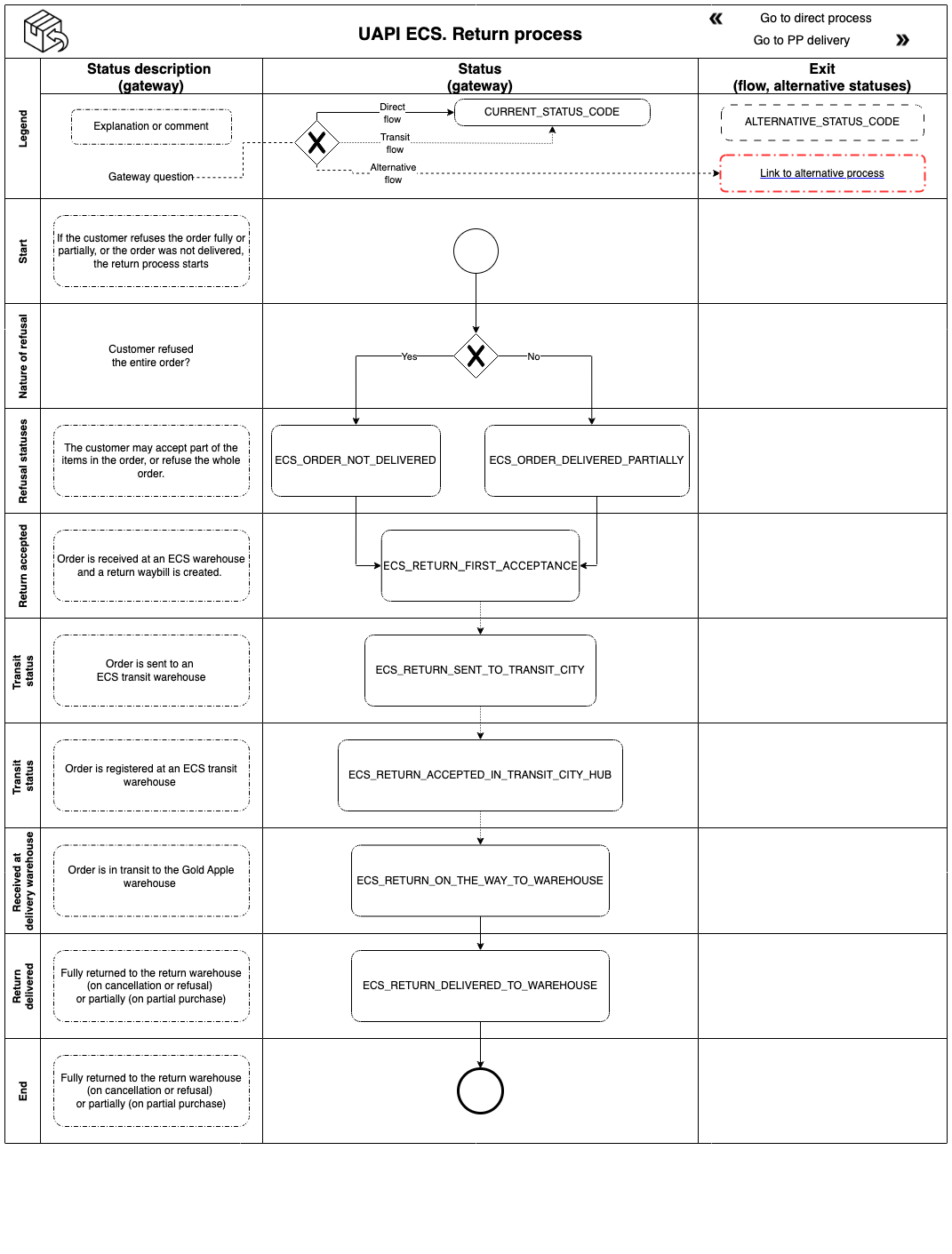
Return Diagram Layer
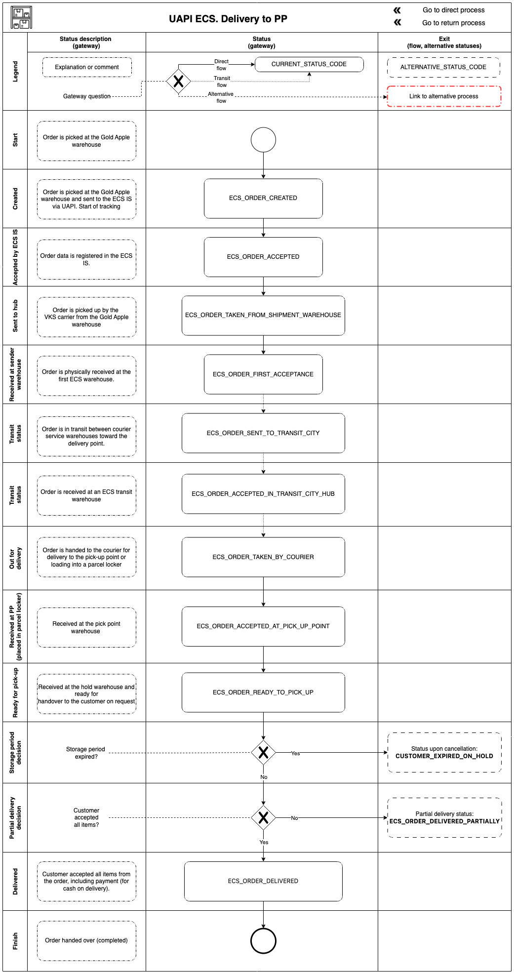
PP Delivery Diagram Layer